Tag Archives: hydraulic dump trailer

China World Class Quality Hydraulic Tipping Trailer, Semi-Trailer Dump Truck, Side Tipper Dump Trailer For Sale axle dump

Use: Truck Trailer
Type: Semi-Trailer
Material: steel
Size: 11000*2500/2550*2850/3250
Max Payload: 50T
Product Name:: Side Wall Tipper Semi trailer
Material:: T700 Steel
LOGO:: According to Customer Requirement
Color: Customers Optional
King pin: 2
Tires: 12.00R22.5
AXle No.&Brand: 3*13Ton Jinduoli/Fuwa Axle
Suspension: Mechanical Suspension
Landing Gear: JINDUOLI 3T,28T,50T/FUWA 28T
Leaf Spring: 90(W)mm*13(Thickness)mm*10(Layer)
Packaging Details: Safety and Economic ShippingExperienced teams choose the most suitable shipping way for different clients among containers, Roro and bulk shipment, balance safety and economic cost.
Port: ZheJiang \HangZhou

Products Description Product Paramenters

product nameSide Wall Dumper Semi trailer
modelKDL9400
inner size10900/10850*2350/2400/2450*600
colorCustom’s Requirement
MaterialT700 steel
king pin2″(50mm)or3.5″(90mm)
axle3*13Ton Jinduoli/Fuwa Axle
suspensionMechanical Suspension
Landing GearJinduoli 3T,28T,50T/FUWA 28T
Product Application Stone Transportation Coal Ore Transportation Recommend Products Rear dump semi trailer Side wall side dump semi trailer Box side dump trailer with skeleton chassis frame Company Profile About usHangZhou Jindoli Special Purpose Vehicle Co., Ltd. was established in 2004,located in HangZhou, ZheJiang province.It is 1 professional Semi trailer supplier and has won the title of ZheJiang Famous Brand and ZheJiang Famous Brand Manufacturer. Carrying your safety and happiness is our mission .Choosing Jindoli company is choosing a better solution of transportation and construction.Our company welcome customers all over the world to visit. Product Line Raw Material Cutting beam Machine Automatic Submerged Arc Welding Welded suspension and assemble chassis Welding the side plate Assemble and welding the side plate Painting Product Certifications Package & Shipment We will choose the most safety and economy shipping solutions, Save cost for our clientsJinduoli worked with experienced shipping companies to ensure the safety of the goods. Shipping terms for your reference: Shipping by containers Shipping by bulk cargo Shipping by Ro ro ship FAQ Q: What’s your MOQ? A: One unit Q: How can I get your trailer? A: I will shipping trailer to your port after you pay money Q:What’s your payment terms? A: 100% TT or L/C before shipping your trailer Q: Can I paint my logo on trailer? A: Of course, you can send me your company logo, then we will design it Contact Information Hi, I am graceWelcome inquiry to our trailers , I will feedback to you ASAP.Phone / Whatsapp: Welcome to send message to my Email: [email protected]’re FULLY WELCOMED COME VISIT our factory!

What Is an Axle?

An axle is the central shaft of a vehicle that rotates a wheel or gear. It may be fixed to the wheels or to the vehicle itself, and can rotate with the wheels and gears. It may include bearings and mounting points. If the axle is fixed to the vehicle, it may have a steering or drive shaft attached.

Rear axle

The rear axle is a crucial part of your vehicle. If it fails to function correctly, it can cause major issues when driving at high speeds. This assembly can be a complicated component, and it is crucial that you find a mechanic who knows how to fix it. Rear axles require periodic gear oil replacement and bearing adjustments.
The rear axle is the final leg of the drivetrain, transferring rotational power from the driveshaft to the rear wheels. While the design of the rear axle varies between vehicles, all axles are designed to follow similar principles. Rear axles may have a single drive shaft or two. The drive shafts are mounted at either end of the axle.
The rear axle ratio is important because it affects how much fuel the truck uses. The lower the ratio, the more fuel-efficient the vehicle is. Higher numbers, like 4:10, are better for towing, but they will decrease fuel economy. When choosing a rear axle ratio, be sure to consider how much weight you’ll be hauling.
The rear axle is the most complicated part of the vehicle. It has many components and may not be easily visible. However, a properly functioning rear axle is essential for maximizing safety and performance. If you have a problem, you should contact a professional for a quick and easy fix. Even minor issues can make a significant difference in how your car or truck functions. A professional will ensure that your vehicle’s rear axle will be up to OEM standards.
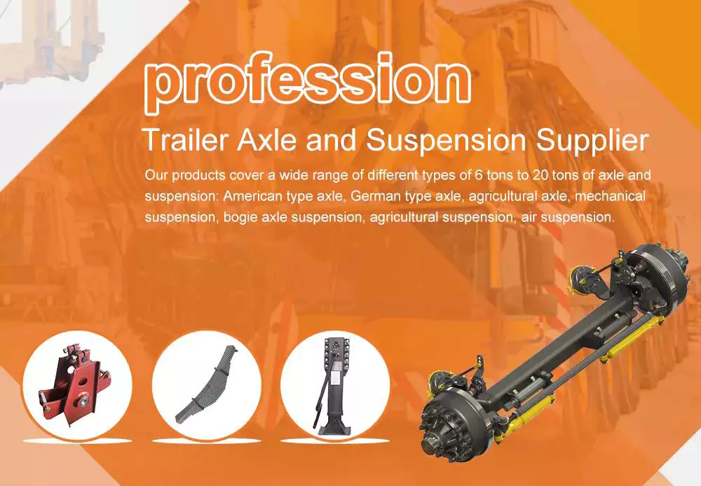
Axles

Semi-floating axle

A semi-floating axle is the next step up from a stub axle. Semi-floating axles have a bearing that supports the shaft, which then floats inside the axle casing. These axles are best suited for midsize trucks. They are also lighter than full-floating axles and can be manufactured at a lower cost.
This design is most commonly found on rear-wheel-drive passenger cars and lighter trucks. The semi-floating design also allows for a wider diameter axle shaft, and it can increase axle capacity by increasing the diameter of the axle shaft. It also has a wider offset to accommodate larger tires. It can accommodate any offset, although this is usually only useful in off-road environments.
Semi-floating axles are often made with a tapered end. This helps keep the axel from twisting while providing traction. The rear hub of a semi-floating axle is usually connected to the axel via a big, strong nut. This nut also provides friction on the axel shaft.
A full-floating axle is common in 3/4-ton and 1/2-ton trucks. It is important to note, however, that almost all factory full-floating rear ends use eight-lug wheels. However, this rule is not strictly enforced and some companies, like Czpt, specialize in semi-floating axles and custom axles.
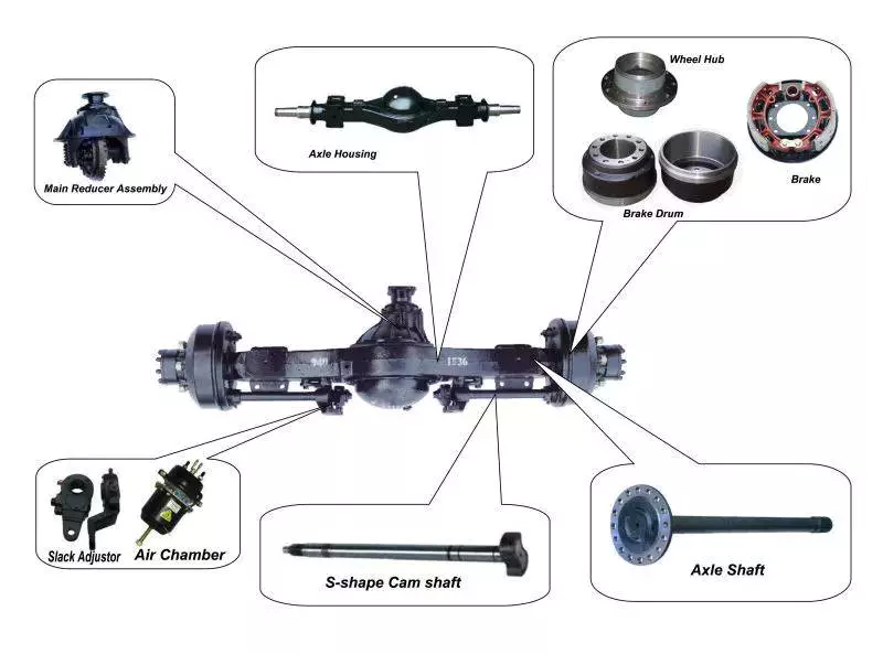
Axles

Drive shaft

A drive shaft is an important part of your vehicle’s drivetrain, which helps to transfer torque from the transmission to the drive wheels. You’ll need to know how it functions in order to properly maintain your car. Fortunately, there are a variety of different parts you can use to upgrade your drive shaft.
In order to improve the performance of your vehicle’s drivetrain, you can replace your existing drive shaft with an upgraded one. These are available in various lengths, so that you can find the right length and fit for your vehicle. Some shafts can even be customized to fit the exact length of your axle.
Generally, short axle shafts are made of solid steel. The longer ones are made of aluminum or carbon fiber. To ensure a smooth and safe ride, they are dynamically balanced to eliminate vibrations. Some models are fitted with giubo joints and universal joints to absorb shock. You can also add flex discs to improve your suspension and dampen the bucking sensation of a drive shaft.
You can tell if your drive shaft needs replacement if you hear a clicking noise while driving. This noise is often audible when the vehicle is turning sharply. You should take your vehicle to a mechanic as soon as you hear this noise, or it could lead to a costly repair. In addition to a clicking noise, your car may also be exhibiting a shuddering or vibrating sensation. If you’re experiencing any of these symptoms, you should take your car in for a checkup by an ASE certified technician. If you ignore these warnings, your car’s drive shaft could separate, causing you a lot of damage.
The drive shaft is attached to the axle flange by a drive shaft bolt. This is an important part of the drivetrain because it’s the only point where the drive shaft will connect to the axle. If the bolt is too long, it could be vulnerable to damage if the washers don’t fit tightly. The drive shaft socket yoke can also be easily damaged when you loosen the bolt.
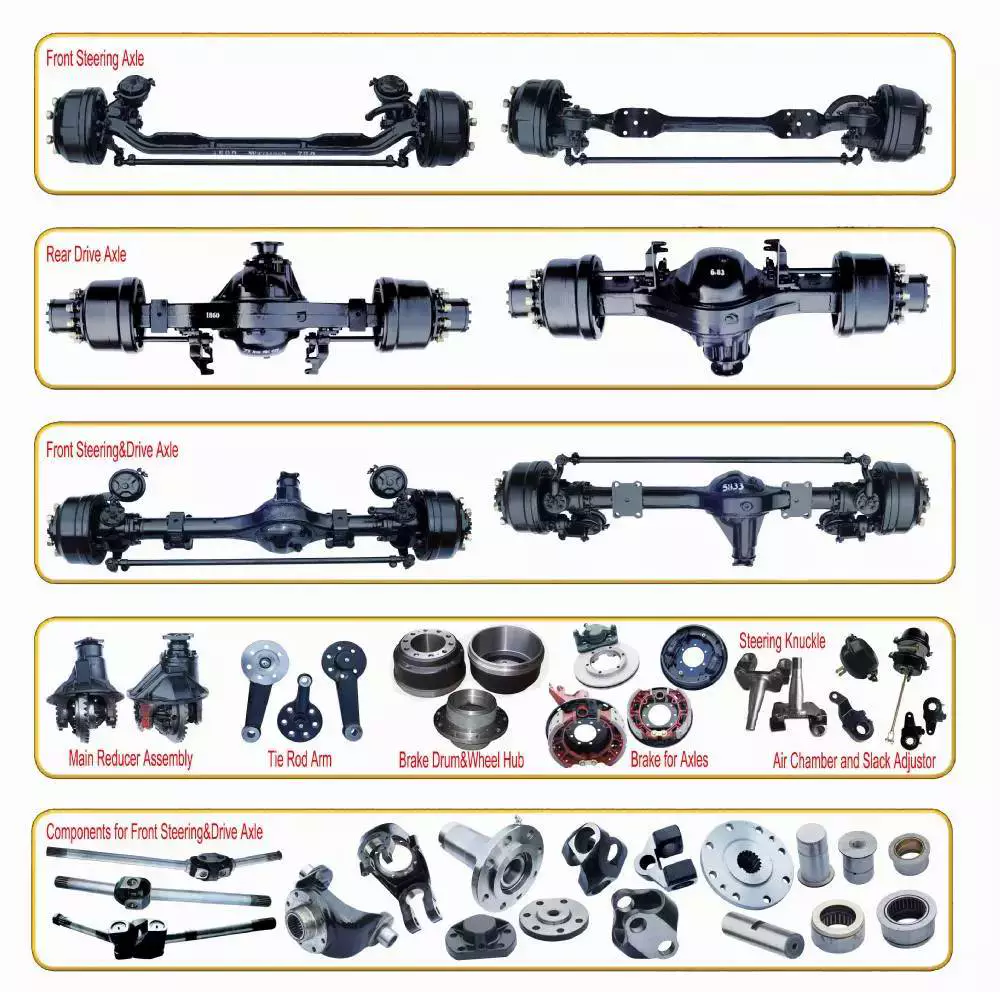
Axles

U-joint

When you replace a u-joint on an axle, you need to take a few things into consideration. One of these considerations is the type of grease you’re going to use. Some of these greases are better than others, and you should always check for a quality grease before you install a new one. A good grease can help to reduce the friction and improve the temperature resistance of the part.
It’s also important to check the u-joint itself. This is the joint between the axle shaft and the wheel. If it’s not functioning properly, it could cause further problems. You should inspect the u-joint every time you change the oil in your vehicle. You can test its lubrication by pressing on the tire with a pry bar or axle stands. You can also try turning the steering wheel fully to test if the joint is loose.
A u-joint failure can leave your car inoperable, which can make driving a risky proposition. If the drive shaft loosens and falls to the ground, you could lose control of your car and risk being stranded. In some severe cases, the front of the driveshaft can even drop to the ground and lift the rear of the car, pushing the car sideways. It’s vital to check u-joints regularly, as failure of the u-joint can cause costly and frustrating car repairs.
When you notice a bad universal joint, you should consider getting it replaced immediately. The most common symptom of a bad u-joint is a clunking sound during acceleration and deceleration. You may also hear vibrations when the u-joint becomes worn and you drive the car. If you notice these symptoms, contact a qualified technician to perform a proper diagnosis.
China World Class Quality Hydraulic Tipping Trailer, Semi-Trailer Dump Truck, Side Tipper Dump Trailer For Sale     axle dumpChina World Class Quality Hydraulic Tipping Trailer, Semi-Trailer Dump Truck, Side Tipper Dump Trailer For Sale     axle dump
editor by czh

China Good quality Heavy Duty 2 Axle 50 Ton U Shape 40 Cubic Dump Tipper Semi Trailer Truck Hydraulic Lifting Axles near me shop

Product Description


Heavy duty 2 axle 50 ton U shape 40 cubic Dump Tipper Semi Trailer Truck Hydraulic lifting axles 
 

Trailer Model 3 Axle 28CBM U Shape Tipper Semi Trailer
Overall dimension(mm) 9300*2500*3400
Inner Dimension(mm) 25 Cubic Meters
Loading capacity 30-80 Tons
Axle brand and number 13T HJ 3units
Kingpin 50# oJOST
Steel Spring leaf spring suspension
Main beam The height of the beam is 500 mm,upper plate is14mm,down plate is 16mm,middle plate is 8mm.
Tyre and quantity 12R22.5 tubeless tires, 12 pieces
Landing gear JOST, double speed operation
Thickness bottom:8mm, side:4mm
Brake system WABCO Braking system
Electrical system 24V Electrical system With LED Light
Tool box 1 Set
Spare tire carrier 1 Set
Painting Optional
Packing Packing
Function Transport Sand and CZPT Transport


QUESTIONS:
1. What’s the deilvery period?
     Answer: 45 days after deposite
2. What’s the shipping way?
    Answer: by roro ship or bulk ship.
3. What’s the MOQ?
    Answer: even 1 pcs is no problem.
4. How could I check the cargo without going there?
    Answer: after production, there will be 1 chassis number, that is single number, we will also                        offer video checking service.


How to Calculate the Diameter of a Worm Gear

worm shaft
In this article, we will discuss the characteristics of the Duplex, Single-throated, and Undercut worm gears and the analysis of worm shaft deflection. Besides that, we will explore how the diameter of a worm gear is calculated. If you have any doubt about the function of a worm gear, you can refer to the table below. Also, keep in mind that a worm gear has several important parameters which determine its working.

Duplex worm gear

A duplex worm gear set is distinguished by its ability to maintain precise angles and high gear ratios. The backlash of the gearing can be readjusted several times. The axial position of the worm shaft can be determined by adjusting screws on the housing cover. This feature allows for low backlash engagement of the worm tooth pitch with the worm gear. This feature is especially beneficial when backlash is a critical factor when selecting gears.
The standard worm gear shaft requires less lubrication than its dual counterpart. Worm gears are difficult to lubricate because they are sliding rather than rotating. They also have fewer moving parts and fewer points of failure. The disadvantage of a worm gear is that you cannot reverse the direction of power due to friction between the worm and the wheel. Because of this, they are best used in machines that operate at low speeds.
Worm wheels have teeth that form a helix. This helix produces axial thrust forces, depending on the hand of the helix and the direction of rotation. To handle these forces, the worms should be mounted securely using dowel pins, step shafts, and dowel pins. To prevent the worm from shifting, the worm wheel axis must be aligned with the center of the worm wheel’s face width.
The backlash of the CZPT duplex worm gear is adjustable. By shifting the worm axially, the section of the worm with the desired tooth thickness is in contact with the wheel. As a result, the backlash is adjustable. Worm gears are an excellent choice for rotary tables, high-precision reversing applications, and ultra-low-backlash gearboxes. Axial shift backlash is a major advantage of duplex worm gears, and this feature translates into a simple and fast assembly process.
When choosing a gear set, the size and lubrication process will be crucial. If you’re not careful, you might end up with a damaged gear or 1 with improper backlash. Luckily, there are some simple ways to maintain the proper tooth contact and backlash of your worm gears, ensuring long-term reliability and performance. As with any gear set, proper lubrication will ensure your worm gears last for years to come.
worm shaft

Single-throated worm gear

Worm gears mesh by sliding and rolling motions, but sliding contact dominates at high reduction ratios. Worm gears’ efficiency is limited by the friction and heat generated during sliding, so lubrication is necessary to maintain optimal efficiency. The worm and gear are usually made of dissimilar metals, such as phosphor-bronze or hardened steel. MC nylon, a synthetic engineering plastic, is often used for the shaft.
Worm gears are highly efficient in transmission of power and are adaptable to various types of machinery and devices. Their low output speed and high torque make them a popular choice for power transmission. A single-throated worm gear is easy to assemble and lock. A double-throated worm gear requires 2 shafts, 1 for each worm gear. Both styles are efficient in high-torque applications.
Worm gears are widely used in power transmission applications because of their low speed and compact design. A numerical model was developed to calculate the quasi-static load sharing between gears and mating surfaces. The influence coefficient method allows fast computing of the deformation of the gear surface and local contact of the mating surfaces. The resultant analysis shows that a single-throated worm gear can reduce the amount of energy required to drive an electric motor.
In addition to the wear caused by friction, a worm wheel can experience additional wear. Because the worm wheel is softer than the worm, most of the wear occurs on the wheel. In fact, the number of teeth on a worm wheel should not match its thread count. A single-throated worm gear shaft can increase the efficiency of a machine by as much as 35%. In addition, it can lower the cost of running.
A worm gear is used when the diametrical pitch of the worm wheel and worm gear are the same. If the diametrical pitch of both gears is the same, the 2 worms will mesh properly. In addition, the worm wheel and worm will be attached to each other with a set screw. This screw is inserted into the hub and then secured with a locknut.

Undercut worm gear

Undercut worm gears have a cylindrical shaft, and their teeth are shaped in an evolution-like pattern. Worms are made of a hardened cemented metal, 16MnCr5. The number of gear teeth is determined by the pressure angle at the zero gearing correction. The teeth are convex in normal and centre-line sections. The diameter of the worm is determined by the worm’s tangential profile, d1. Undercut worm gears are used when the number of teeth in the cylinder is large, and when the shaft is rigid enough to resist excessive load.
The center-line distance of the worm gears is the distance from the worm centre to the outer diameter. This distance affects the worm’s deflection and its safety. Enter a specific value for the bearing distance. Then, the software proposes a range of suitable solutions based on the number of teeth and the module. The table of solutions contains various options, and the selected variant is transferred to the main calculation.
A pressure-angle-angle-compensated worm can be manufactured using single-pointed lathe tools or end mills. The worm’s diameter and depth are influenced by the cutter used. In addition, the diameter of the grinding wheel determines the profile of the worm. If the worm is cut too deep, it will result in undercutting. Despite the undercutting risk, the design of worm gearing is flexible and allows considerable freedom.
The reduction ratio of a worm gear is massive. With only a little effort, the worm gear can significantly reduce speed and torque. In contrast, conventional gear sets need to make multiple reductions to get the same reduction level. Worm gears also have several disadvantages. Worm gears can’t reverse the direction of power because the friction between the worm and the wheel makes this impossible. The worm gear can’t reverse the direction of power, but the worm moves from 1 direction to another.
The process of undercutting is closely related to the profile of the worm. The worm’s profile will vary depending on the worm diameter, lead angle, and grinding wheel diameter. The worm’s profile will change if the generating process has removed material from the tooth base. A small undercut reduces tooth strength and reduces contact. For smaller gears, a minimum of 14-1/2degPA gears should be used.
worm shaft

Analysis of worm shaft deflection

To analyze the worm shaft deflection, we first derived its maximum deflection value. The deflection is calculated using the Euler-Bernoulli method and Timoshenko shear deformation. Then, we calculated the moment of inertia and the area of the transverse section using CAD software. In our analysis, we used the results of the test to compare the resulting parameters with the theoretical ones.
We can use the resulting centre-line distance and worm gear tooth profiles to calculate the required worm deflection. Using these values, we can use the worm gear deflection analysis to ensure the correct bearing size and worm gear teeth. Once we have these values, we can transfer them to the main calculation. Then, we can calculate the worm deflection and its safety. Then, we enter the values into the appropriate tables, and the resulting solutions are automatically transferred into the main calculation. However, we have to keep in mind that the deflection value will not be considered safe if it is larger than the worm gear’s outer diameter.
We use a four-stage process for investigating worm shaft deflection. We first apply the finite element method to compute the deflection and compare the simulation results with the experimentally tested worm shafts. Finally, we perform parameter studies with 15 worm gear toothings without considering the shaft geometry. This step is the first of 4 stages of the investigation. Once we have calculated the deflection, we can use the simulation results to determine the parameters needed to optimize the design.
Using a calculation system to calculate worm shaft deflection, we can determine the efficiency of worm gears. There are several parameters to optimize gearing efficiency, including material and geometry, and lubricant. In addition, we can reduce the bearing losses, which are caused by bearing failures. We can also identify the supporting method for the worm shafts in the options menu. The theoretical section provides further information.

China Good quality Heavy Duty 2 Axle 50 Ton U Shape 40 Cubic Dump Tipper Semi Trailer Truck Hydraulic Lifting Axles   near me shop China Good quality Heavy Duty 2 Axle 50 Ton U Shape 40 Cubic Dump Tipper Semi Trailer Truck Hydraulic Lifting Axles   near me shop

China high quality Superlink Side Dump Trailer 3+3 Axles with 2 Dolly Connect Double Towing Semi Hydraulic Tipper Trailer near me manufacturer

Product Description

PRODUCT DESCRIPTION
————————————-

DOUBLE TIPPER SEMI TRAILER
TIPPING WAYS MADE BY REQUEST
AXLE NO. AXLE LOCATION TIRE NO. LENGTH RATING CAPACITY
1 REAR 4 4000-7500MM 15TONS
2 1+1 8 7500-12500MM 40TONS
3 1+2 12 12500-15000MM 60TONS
4 2+2 16 15000-18000MM 80TONS
SUSPENSION AMERICA TYPE MECHANICAL SUSPENSION
  WHEEL 11:00 R20
  TURNTABLE DIAMETER IS 1100MM
  TRACTION HOOK DN50
  TRACTION BAR LENGTH IS 1.4M  
  DIMENSIONS(LXWXH) 7500-18000×2500×1500MM
  STEEL SPRING 10/10 PIECES PER AXLES
TIRE:  
  THE MATERIAL OF 
MAIN BEAM
THE HEIGHT OF THE BEAM IS420MM,UPPER PLATE IS 12MM*140,DOWN PLATE IS 12*140MM,MIDDLE PLATE IS 6MM(STRICTLY).MADE OF Q345
  PLATFORM PLATE 3MM CZPT PLATE
BRAKE: WABCO VALVE
  BRAKE KEMI BRAND OF CHINA
  BRAKE CHAMBER TWO DOUBLE AND TWO SINGLE CHAMBER( TKL BRAND  )
  ABS SYSTEM WITH
ELECTRICAL:  
  VOLTAGE 24V
  RECEPTACLE 7 WAYS(7 WIRE HARNESS)
LIGHT COLOR: (LED LIGHT)
  SIDE MARKER LAMP ORANGE
  REAR LAMP RED
  TURN SIGNAL LAMP ORANGE
MISCELLANEOUS:  
  PAINTING CAN BE CHOOSE FREELY
  MARKING ACCORDING TO THE REQUIREMENT OF THE BUYER
  SIDE GUARD ACCORDING TO THE REQUIREMENT OF THE BUYER
  TOOLS BOX ONE PIECES OR ACCORDING TO THE BUYER(1M LENGTH)
   WATER TANK THE SIZE CAN BE CHOOSE FREELY.

PRODUCTION & DETAILS
———————————————

     COLOR & AXLE QTY CAN BE MADE BY CLIENT NEED AFTER CONTACTING OUR SALES

RELATED PRODUCTS
———————————————

CASES FOR EXPORTING
———————————————

FAQ
———————————————

1. How To Buy From Us ?

– You Can Select The Desired Products From Our Online Shop,

A. Clicking Our Sales Manager To Confirm The Model;

B. Telling Our Sales Manager Special Request If You Have;

C. Confirmed The Quantity And Price On The Desired Model;

D. Confirming The Terms Of Delivery (Fob/Cfr/Cif/Daf.. Etc By Mutual Agreement);

E. Our Sales Manager Can Issue You The Commercial Invoice On Agreement;

F. 1st Down Payment 30% On Total Invoice Value Should To Paid Us By Tt/Online Upon The Invoice Issuing.

G. Our Factory Will Finish The Production According To The Agreed Production Time.

H. Final Payment Will Be Paid After We Showing All Production As Per Clients’ Need.

I. Shipment Arrange And Final Document Arrange To Customer.

2. What’s The Guarantee Period On Our Products ?

– All Products We Export Has 1 Year Guarantee Period, And For The Beam Is Lifetime Promise. As Exporting Experience For Years, All Products From Our Factory Can Meet The Exporting Country’s Standards On Vehicles, All Vehicles Will Be

Built Upon The Related Countries’ Road Condition, And Our Sales Manager Will Provide Customer The Best Suggestions Before Placing The Order. If Some Easy Weary Small Parts, We Can Offer Free In 6 Months.

3. If Customized Service Provided ?

– Yes, Please Contact Our Sales Manger, We Can Offer Customized Service On Vehicle Design / Painting, Etc.

– Oem Available

4. If Our Vehicle/Trailer Can Couple With Your Tractor Head ?

– 90% Of The Truck In The Market Can Coupling With Our Vehicle, As Howo, Shacman, Beiben, Volve…

– If Other Brand Truck Head, Please Inform Our Sales Manager Before Order Placing, We Need To Adjust The Height And Overhang To Couple With The Using Truck.

5. Whats The Time For Delivery & Arrival  ?

– If Standard Model We Have In Stock Can Ship It Out Within 10 Days After Payment.

– If It Belongs To Customize Series, Ordinary Cases In 15 Days Can Be Finished For Shipment.

– For Asian Countries, Ship Can Be Reached In 1-2 Weeks, If For African & Mid East & European Countries, 25 Workdays Will Be Achieved.

6. If We Can Provide Terms For Reducing Your Import Duties ?

– Yes, Please Contact With Us, We Are Nationalized Manufacture With Tax Reduction, Will Also Offer You The Best Way For Import Duty Reduction.

PACKING &SHIPPING
———————————————

COMPANY INFORMATION
———————————————

TRADE SHOW
———————————————

CONTACT US
———————————————

The Benefits of Spline Couplings for Disc Brake Mounting Interfaces

Spline couplings are commonly used for securing disc brake mounting interfaces. Spline couplings are often used in high-performance vehicles, aeronautics, and many other applications. However, the mechanical benefits of splines are not immediately obvious. Listed below are the benefits of spline couplings. We’ll discuss what these advantages mean for you. Read on to discover how these couplings work.

Disc brake mounting interfaces are splined

There are 2 common disc brake mounting interfaces – splined and six-bolt. Splined rotors fit on splined hubs; six-bolt rotors will need an adapter to fit on six-bolt hubs. The six-bolt method is easier to maintain and may be preferred by many cyclists. If you’re thinking of installing a disc brake system, it is important to know how to choose the right splined and center lock interfaces.
splineshaft

Aerospace applications

The splines used for spline coupling in aircraft are highly complex. While some previous researches have addressed the design of splines, few publications have tackled the problem of misaligned spline coupling. Nevertheless, the accurate results we obtained were obtained using dedicated simulation tools, which are not commercially available. Nevertheless, such tools can provide a useful reference for our approach. It would be beneficial if designers could use simple tools for evaluating contact pressure peaks. Our analytical approach makes it possible to find answers to such questions.
The design of a spline coupling for aerospace applications must be accurate to minimize weight and prevent failure mechanisms. In addition to weight reduction, it is necessary to minimize fretting fatigue. The pressure distribution on the spline coupling teeth is a significant factor in determining its fretting fatigue. Therefore, we use analytical and experimental methods to examine the contact pressure distribution in the axial direction of spline couplings.
The teeth of a spline coupling can be categorized by the type of engagement they provide. This study investigates the position of resultant contact forces in the teeth of a spline coupling when applied to pitch diameter. Using FEM models, numerical results are generated for nominal and parallel offset misalignments. The axial tooth profile determines the behavior of the coupling component and its ability to resist wear. Angular misalignment is also a concern, causing misalignment.
In order to assess wear damage of a spline coupling, we must take into consideration the impact of fretting on the components. This wear is caused by relative motion between the teeth that engage them. The misalignment may be caused by vibrations, cyclical tooth deflection, or angular misalignment. The result of this analysis may help designers improve their spline coupling designs and develop improved performance.
CZPT polyimide, an abrasion-resistant polymer, is a popular choice for high-temperature spline couplings. This material reduces friction and wear, provides a low friction surface, and has a low wear rate. Furthermore, it offers up to 50 times the life of metal on metal spline connections. For these reasons, it is important to choose the right material for your spline coupling.
splineshaft

High-performance vehicles

A spline coupler is a device used to connect splined shafts. A typical spline coupler resembles a short pipe with splines on either end. There are 2 basic types of spline coupling: single and dual spline. One type attaches to a drive shaft, while the other attaches to the gearbox. While spline couplings are typically used in racing, they’re also used for performance problems.
The key challenge in spline couplings is to determine the optimal dimension of spline joints. This is difficult because no commercial codes allow the simulation of misaligned joints, which can destroy components. This article presents analytical approaches to estimating contact pressures in spline connections. The results are comparable with numerical approaches but require special codes to accurately model the coupling operation. This research highlights several important issues and aims to make the application of spline couplings in high-performance vehicles easier.
The stiffness of spline assemblies can be calculated using tooth-like structures. Such splines can be incorporated into the spline joint to produce global stiffness for torsional vibration analysis. Bearing reactions are calculated for a certain level of misalignment. This information can be used to design bearing dimensions and correct misalignment. There are 3 types of spline couplings.
Major diameter fit splines are made with tightly controlled outside diameters. This close fit provides concentricity transfer from the male to the female spline. The teeth of the male spline usually have chamfered tips and clearance with fillet radii. These splines are often manufactured from billet steel or aluminum. These materials are renowned for their strength and uniform grain created by the forging process. ANSI and DIN design manuals define classes of fit.
splineshaft

Disc brake mounting interfaces

A spline coupling for disc brake mounting interfaces is a type of hub-to-brake-disc mount. It is a highly durable coupling mechanism that reduces heat transfer from the disc to the axle hub. The mounting arrangement also isolates the axle hub from direct contact with the disc. It is also designed to minimize the amount of vehicle downtime and maintenance required to maintain proper alignment.
Disc brakes typically have substantial metal-to-metal contact with axle hub splines. The discs are held in place on the hub by intermediate inserts. This metal-to-metal contact also aids in the transfer of brake heat from the brake disc to the axle hub. Spline coupling for disc brake mounting interfaces comprises a mounting ring that is either a threaded or non-threaded spline.
During drag brake experiments, perforated friction blocks filled with various additive materials are introduced. The materials included include Cu-based powder metallurgy material, a composite material, and a Mn-Cu damping alloy. The filling material affects the braking interface’s wear behavior and friction-induced vibration characteristics. Different filling materials produce different types of wear debris and have different wear evolutions. They also differ in their surface morphology.
Disc brake couplings are usually made of 2 different types. The plain and HD versions are interchangeable. The plain version is the simplest to install, while the HD version has multiple components. The two-piece couplings are often installed at the same time, but with different mounting interfaces. You should make sure to purchase the appropriate coupling for your vehicle. These interfaces are a vital component of your vehicle and must be installed correctly for proper operation.
Disc brakes use disc-to-hub elements that help locate the forces and displace them to the rim. These elements are typically made of stainless steel, which increases the cost of manufacturing the disc brake mounting interface. Despite their benefits, however, the high braking force loads they endure are hard on the materials. Moreover, excessive heat transferred to the intermediate elements can adversely affect the fatigue life and long-term strength of the brake system.

China high quality Superlink Side Dump Trailer 3+3 Axles with 2 Dolly Connect Double Towing Semi Hydraulic Tipper Trailer   near me manufacturer China high quality Superlink Side Dump Trailer 3+3 Axles with 2 Dolly Connect Double Towing Semi Hydraulic Tipper Trailer   near me manufacturer

China Professional Customized Self Dumping Dump Semi Trailer 2 Axles with Hydraulic Cylinder wholesaler

Product Description

U Style Jushixin 2 Axles 8 wheelers Mining Dump Semi Trailer

Product Description

The shape of the car body is beautiful, and the internal space is spacious; the front windshield is laminated with glass, and the upper part is darkened to avoid glare.

Application of multi-function steering wheel, LCD touch screen car multimedia, cup holder,

ashtray complete configuration.

Electrical components: waterproof, dustproof, shockproof, better performance;

Gearbox: standard gearbox, high transmission efficiency, smooth shifting;

Axles: The front and rear axles of CZPT are used, which are reliable in quality and durable;

Drive shaft: thicker drive shaft, larger transmission torque and longer life.

It is suitable for short distance transportation of concrete, sand, earth, coal, ore and other bulk materials such as construction, water conservancy, road construction and mining. The main characteristics of the dump truck project

In civil engineering, dump trucks often work in conjunction with excavators, loaders, belt conveyors and other construction machinery to form a loading, transportation, and unloading production line to carry out the loading and unloading and transportation of earth, sand, and bulk materials.

Product Parameters

Product Overview
Product name 2 Axles Semi Trailer
Model JSXT3494
Transport medium sand stones and earth
Dimensions (mm) 10000×2520×3600
Box size (mm) 6800×2300×1650
Product parameters (main configuration)
Cabinet material Side Q235B/6.0mm;
Bottom Q235B/8.0mm
Beam material Q235B
Shape Rectangle
Engine Weichai WD615.47
Frame 300*60*8 3 layers
Front / rear suspension (mm) Front:1540
Rear: 1635
Departure corner Front: 30;
Rear :27
Suspension Leaf spring 9/10
Leaf spring Front:9
Rear:10
Number of axles 4
Wheelbase (mm) 1950+3825+1350
Number of tires 12+1
Tread (mm) 2040/1850/1850
Tire specifications 12.00R20
ABS Yes
A/C Yes
Sleeper Yes; 1
Suspension Leaf spring

Detailed Photos


Truck FAQ

Q1. What is the minimum order quantity? Can the product be customized?
A1:our MOQ is 1 unit. and yes, we can customized,we can produce trucks according to your special needs or requirements.

Q2. What should I do if I have problems during the use of the truck?
A2: We can supply English manual book and also take a video for showing how to resolve the problems, and you can also buy some spare parts together with your trucks.

Q3. How long is your delivery time?
A3: Trucks production time is about 20-30 working days.

Q4. What is your after-sales service system?
A4: trucks for 12 months warranty. Lifetime free technical consulting services and long-term factory price accessories support.

Q5: What are the modes of transportation?
A5: We can choose the Break Bulk, RORO, FR transportation and land transportation according to truck type and destination country.

Q6: What are the payment terms for trucks?
A6: We provide the EXW,FOB,CIF, DDU, DDP,etc.according to the specific situation.

Q7: Which brand of the trucks will you prefer to purchase?
A7: You can choose the brand of the HOWO, Sinotruk, Xihu (West Lake) Dis.feng, Shacman, CZPT etc.

Q8: Is it available to print our own brand on our truck?
A8: Totally acceptable as you wish.

Related Products

Company Profile

Certifications

Cooperation Brand

Packaging & Shipping

The 5 components of an axle, their function and installation

If you’re considering replacing an axle in your vehicle, you should first understand what it is. It is the component that transmits electricity from 1 part to another. Unlike a fixed steering wheel, the axles are movable. The following article will discuss the 5 components of the half shaft, their function and installation. Hopefully you were able to identify the correct axle for your vehicle. Here are some common problems you may encounter along the way.
Driveshaft

five components

The 5 components of the shaft are flange, bearing surface, spline teeth, spline pitch and pressure angle. The higher the number of splines, the stronger the shaft. The maximum stress that the shaft can withstand increases with the number of spline teeth and spline pitch. The diameter of the shaft times the cube of the pressure angle and spline pitch determines the maximum stress the shaft can withstand. For extreme load applications, use axles made from SAE 4340 and SAE 1550 materials. In addition to these 2 criteria, spline rolling produces a finer grain structure in the material. Cutting the splines reduces the strength of the shaft by 30% and increases stress.
The asymmetric length of the shaft implies different torsional stiffness. A longer shaft, usually the driver’s side, can handle more twist angles before breaking. When the long axis is intact, the short axis usually fails, but this does not always happen. Some vehicles have short axles that permanently break, causing the same failure rate for both. It would be ideal if both shafts were the same length, they would share the same load.
In addition to the spline pitch, the diameter of the shaft spline is another important factor. The small diameter of a spline is the radius at which it resists twisting. Therefore, the splines must be able to absorb shock loads and shocks while returning to their original shape. To achieve these goals, the spline pitch should be 30 teeth or less, which is standard on Chrysler 8.75-inch and GM 12-bolt axles. However, a Ford 8.8-inch axle may have 28 or 31 tooth splines.
In addition to the CV joints, the axles also include CV joints, which are located on each end of the axle. ACV joints, also known as CV joints, use a special type of bearing called a pinion. This is a nut that meshes with the side gear to ensure proper shaft alignment. If you notice a discrepancy, take your car to a shop and have it repaired immediately.

Function

Axles play several important roles in a vehicle. It transfers power from the transmission to the rear differential gearbox and the wheels. The shaft is usually made of steel with cardan joints at both ends. Shaft Shafts can be stationary or rotating. They are all creatures that can transmit electricity and loads. Here are some of their functions. Read on to learn more about axles. Some of their most important features are listed below.
The rear axle supports the weight of the vehicle and is connected to the front axle through the axle. The rear axle is suspended from the body, frame and axle housing, usually spring loaded, to cushion the vehicle. The driveshaft, also called the propshaft, is located between the rear wheels and the differential. It transfers power from the differential to the drive wheels.
The shaft is made of mild steel or alloy steel. The latter is stronger, more corrosion-resistant and suitable for special environments. Forged for large diameter shafts. The cross section of the shaft is circular. While they don’t transmit torque, they do transmit bending moment. This allows the drive train to rotate. If you’re looking for new axles, it’s worth learning more about how they work.
The shaft consists of 3 distinct parts: the main shaft and the hub. The front axle assembly has a main shaft, while the rear axle is fully floating. Axles are usually made of chrome molybdenum steel. The alloy’s chromium content helps the axle maintain its tensile strength even under extreme conditions. These parts are welded into the axle housing.
Driveshaft

Material

The material used to make the axle depends on the purpose of the vehicle. For example, overload shafts are usually made of SAE 4340 or 1550 steel. These steels are high strength low alloy alloys that are resistant to bending and buckling. Chromium alloys, for example, are made from steel and have chromium and molybdenum added to increase their toughness and durability.
The major diameter of the shaft is measured at the tip of the spline teeth, while the minor diameter is measured at the bottom of the groove between the teeth. These 2 diameters must match, otherwise the half shaft will not work properly. It is important to understand that the brittleness of the material should not exceed what is required to withstand normal torque and twisting, otherwise it will become unstable. The material used to make the axles should be strong enough to carry the weight of a heavy truck, but must also be able to withstand torque while still being malleable.
Typically, the shaft is case hardened using an induction process. Heat is applied to the surface of the steel to form martensite and austenite. The shell-core interface transitions from compression to tension, and the peak stress level depends on the process variables used, including heating time, residence time, and hardenability of the steel. Some common materials used for axles are listed below. If you’re not sure which material is best for your axle, consider the following guide.
The axle is the main component of the axle and transmits the transmission motion to the wheels. In addition, they regulate the drive between the rear hub and the differential sun gear. The axle is supported by axle bearings and guided to the path the wheels need to follow. Therefore, they require proper materials, processing techniques and thorough inspection methods to ensure lasting performance. You can start by selecting the material for the shaft.
Choosing the right alloy for the axle is critical. You will want to find an alloy with a low carbon content so it can harden to the desired level. This is an important consideration because the hardenability of the alloy is important to the durability and fatigue life of the axle. By choosing the right alloy, you will be able to minimize these problems and improve the performance of your axle. If you have no other choice, you can always choose an alloy with a higher carbon content, but it will cost you more money.
Driveshaft

Install

The process of installing a new shaft is simple. Just loosen the axle nut and remove the set bolt. You may need to tap a few times to get a good seal. After installation, check the shaft at the points marked “A” and “D” to make sure it is in the correct position. Then, press the “F” points on the shaft flange until the points are within 0.002″ of the runout.
Before attempting to install the shaft, check the bearings to make sure they are aligned. Some bearings may have backlash. To determine the amount of differential clearance, use a screwdriver or clamp lever to check. Unless it’s caused by a loose differential case hub, there shouldn’t be any play in the axle bearings. You may need to replace the differential case if the axles are not mounted tightly. Thread adjusters are an option for adjusting drive gear runout. Make sure the dial indicator is mounted on the lead stud and loaded so that the plunger is at right angles to the drive gear.
To install the axle, lift the vehicle with a jack or crane. The safety bracket should be installed under the frame rails. If the vehicle is on a jack, the rear axle should be in the rebound position to ensure working clearance. Label the drive shaft assemblies and reinstall them in their original positions. Once everything is back in place, use a 2-jaw puller to pry the yoke and flange off the shaft.
If you’ve never installed a half shaft before, be sure to read these simple steps to get it right. First, check the bearing surfaces to make sure they are clean and undamaged. Replace them if they look battered or dented. Next, remove the seal attached to the bushing hole. Make sure the shaft is installed correctly and the bearing surfaces are level. After completing the installation process, you may need to replace the bearing seals.

China Professional Customized Self Dumping Dump Semi Trailer 2 Axles with Hydraulic Cylinder   wholesaler China Professional Customized Self Dumping Dump Semi Trailer 2 Axles with Hydraulic Cylinder   wholesaler