Tag Archives: drum type shaft

China American Type Trailer Axle Shaft Outboard Drum Trailer Steering Axle axle bar

Product Description

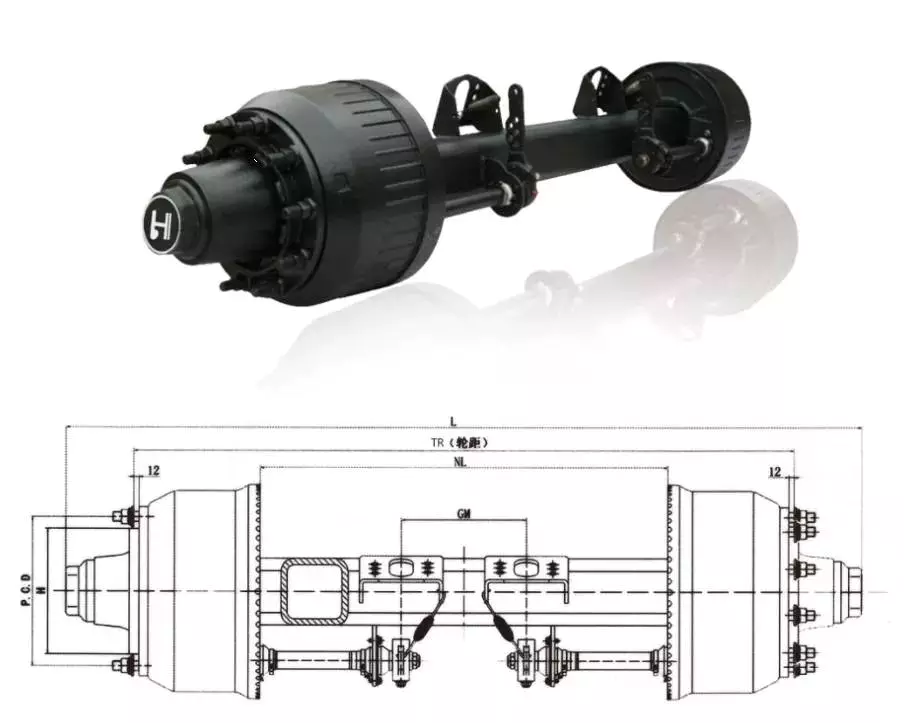
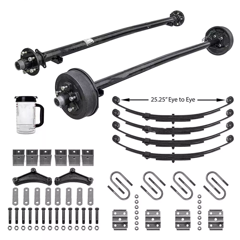
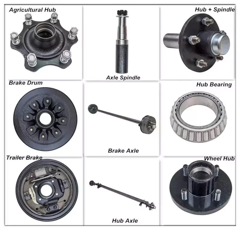
American Type Trailer axle shaft Outboard Drum Trailer Steering Axle

Specification
Use Trailer Parts
OE NO. American Type Trailer axle shaft Outboard Drum Trailer Steering Axle
Max Payload 13T/16T
Size 150*150
Origin ZheJiang ,China
Track 1840/1850/2050/2150

AMERICAN TYPE BRAKE DRUM SERIES
1. Special heat treatment, low alloy steel axle beam, strong bearing capacity, low dead weight.

2. High quality alloy solid spindle provides superior fatigue resistance through integral heat treatment.
3. Camshaft adopts special sealing processing to ensure that grease will not enter the brake drum, which is more safe.

4. New tight fit wheel hub cap, O-ring seal, good sealing performance.


To Be Negotiated 1 Piece
(Min. Order)

###

After-sales Service: 1 Year
Condition: New
Axle Number: 1
Application: Trailer
Certification: ISO
Material: Steel

###

Customization:

###

Specification
Use Trailer Parts
OE NO. American Type Trailer axle shaft Outboard Drum Trailer Steering Axle
Max Payload 13T/16T
Size 150*150
Origin Shandong,China
Track 1840/1850/2050/2150

Types of Axles

An axle is the central shaft of a rotating wheel or gear. It can be fixed to the wheels or to the vehicle itself. Depending on the design, it may be fixed in different positions and have different types of mounting points. It may also have bearings. Axles come in different types and shapes. Some of them are more functional than others, and they may be semi-floating, tandem-drive, or lift axles.

Customized axles work best for cars

Adding big horsepower to a car can increase its performance, but this addition can also cause problems. It is important to take proper measurements for the rear axle to ensure it is not too long or too short. However, this measurement can become complicated with limited-slip differentials and offset pinions.
If you want to add custom axles to your car, it is important to know the physical properties of the axle and what kind of load it can handle. If you’re only planning to make a minor upgrade, it may be enough to get a standard axle. However, if you’re planning to make any major modifications, a customized axle will be a much better option.
Customized axles can be made of a variety of materials. They can be made of carbon steel or nickel steel. Some are made to float freely and others are made to be rigid. If you’re building a car, you should also consider the type of bearings and kingpins that it will use.
Axles come in a variety of types, based on the amount of force they produce. Some are pre-defined, while others are customized to meet your car’s specifications. The advantages of customizing your axles include improved wheel speed and torque. You can even adjust the angle of the axles for even more performance.
Axles can make or break your car’s performance. Customized axles are made with a proprietary alloy material that increases the torsional strength. Because of this, they are able to withstand a tremendous amount of power. Additionally, they are able to withstand lateral and bending loads.
While customizing your axle is an excellent idea, it is also very expensive. The best way to go about it is to work with a professional. They are able to make the axles you need and they’re usually well-made and made of quality materials. However, you should make sure you check the reviews and ratings of the manufacturer before making a purchase.
If you want to shorten the axle on your car, you should have it machined with new splines. The number of splines on an axle is important because it determines the strength of the axle. A 33-spline axle is more durable than a 28-spline axle, and a 40-spline axle is even stronger.
Axles

Semi-floating axles

Semi-floating rear axles are a common type of axle used in midsize trucks. They utilize a single wheel support bearing and use one axle shaft to transmit rotation to the wheels. A semi-floating axle is typically lubricated. Aftermarket kits are available to make the axle shaft stronger. However, these kits do not upgrade the axle differential assembly. Therefore, axles with weak differential assemblies may not benefit from conversion.
Semi-floating axles feature a “C-Clip” for holding the axle shaft in place in the axle casing. The problem with this design is that the axle shaft is exposed to more wear and tear. In addition, axle shafts with a C-Clip must be surface-hardened in the area where the axle shaft is flexed.
Semi-floating axles differ from full-floating axles in their appearance. A semi-floating axle has a hub that looks like the hub of a 3/4-ton 14-bolt Ford axle, whereas a full-floating axle’s hub looks like that of a 1 ton Ford axle.
Semi-floating axles have a tapered end. This makes them more efficient in carrying weight. In addition, they have a keyed end to prevent the rear hub from slipping around. This ensures the axle remains stable even when the rear wheels are turning. It is also important to note that semi-floating axles can only carry a small amount of weight, while full-floating axles can carry a lot of weight.
Semi-floating axles are lighter than full-float axles, which makes them less expensive to manufacture. Additionally, if one axle fails, the vehicle will continue to operate normally. Aside from this, semi-floating axles also have c-clips, which are the bearings that bear the weight of the vehicle.
A semi-floating axle is also available with an optional 5-lug hub. The axle shaft transmits rotational torque from the differential to the wheel, and the hub rides on tapered roller bearings. A full-floating axle assembly is stronger than a semi-floating axle system. In addition, it is compatible with factory 5-lug hubs.
Semi-floating axles are easier to install than full-floating axles. However, if you want to convert your semi-floating axle to a full-floating axle, you can install an aftermarket kit.
Axles

Tandem-drive axles

A tandem drive axle is a type of axle with two wheels on one side of the vehicle. Compared to a single axle with two wheels, a tandem drive axle is 60 pounds lighter and offers improved performance and durability. This type of axle is designed to optimize fleet uptime by balancing design efficiency and application-specific demands.
The suspension system of a tandem drive axle includes air springs that control the suspension of the lead and trailing axles. The air springs are pneumatically connected to a common reservoir. The springs’ displacements are averaged to provide a controlling input to the air spring pressurization controller.
A tandem drive axle may be used to transport heavier loads. It is important to note that the maximum weight of a tandem drive axle may be different in different states. In general, the federal regulations allow up to 34K pounds per axle, but the state regulations may be different. However, the weight limits of tandem axle groups are significantly lower than for single axles.
A tandem drive axle is a common type of vehicle drive axle. It is characterized by two axles spaced more than 40 inches apart. The distances are measured from the axle centers. A tandem-drive axle may be a drive axle or a steer axle. If the steer axle is overloaded, steering will be more difficult.
A tandem drive axle is a popular choice for commercial trucks. It is durable and can handle heavy loads. It is often used in cement mixing trucks and tanker trucks, where the weight of the load is distributed evenly between the two axles. The combination of the two axles helps a tandem drive truck make a smoother start from a stopped position. Because the weight is distributed across two axles, the torque generated by the engine can be distributed more effectively.
A tandem drive axle is usually paired with two air-lift axles. A tandem drive axle is also used when the weight of a cargo truck cannot be supported by the two air-lift axles. Tandem-drive axles are typically installed at the rear of a truck’s chassis.
Axles

Lift axles

Lift axles are a great way to reduce the workload on your powertrain, while also improving your fuel economy. These axles reduce rolling resistance, thrust, and tandem scrub, and can improve fuel economy by two to five percent. However, you should use lift axles with care, and pay special attention to suspension spacing.
Some lift axles have a steering feature, which allows the driver to control when the axle is raised, which is useful for taking sharp corners. However, some drawbacks to non-steerable lift axles include excessive tire wear. Steerable lift axles can alleviate this problem, but they are generally more expensive.
Another benefit of lift axles is that they increase a vehicle’s weight carrying capacity. This is useful for trucks with large load capacities. Although state laws vary, federal regulations are generally in favor of spreading the weight of a truck’s cargo across several axles. This helps protect large road pavements and bridges.
Lift axles are an important feature of dump trucks and should be considered if you’re considering making a change. However, they can be costly, and it’s important to consider the costs and benefits before deciding on a new configuration. These axles are best used when the load capacity of a truck is more than double what it is capable of carrying.
The developed algorithm has been tested under various scenarios. First, the algorithm accepts the command from the driver to lift axles. However, it ignores the tag axle dropping command if the vehicle is traveling more than 30 kph. Second, the vehicle stops for about 60 seconds. Once loaded, the algorithm drops the axles in order.
Besides enhancing the weight carrying capacity of a truck, lift axles are also used for auxiliary purposes. Most of these axles are used on dump trucks. In addition to the pusher axle, some dump trucks have a tag axle, which increases the distance between the steer axle and rearmost axle. This allows the truck to carry more cargo than the pusher axle.
China American Type Trailer Axle Shaft Outboard Drum Trailer Steering Axle     axle barChina American Type Trailer Axle Shaft Outboard Drum Trailer Steering Axle     axle bar
editor by czh 2022-11-30

China Hot selling Hot Selling American Type Trailer Axle Shaft Outboard Drum Trailer Steering Axle with Free Design Custom

Product Description

Item Length (mm) Wheel Base(mm) Width of the Trailer(mm) Loading Weight(kg)
CJAR330 1500 1370 1550 780
CJAR520 1700 1570 1750 1000
CJAR580 2000 1870 2100 1700

HangZhouU Machinery Co., Ltd. is located in the hometown of civilized trailers at home and abroad. It is a modern
comprehensive enterprise integrating design, research and development, production and sales. Since its establishment,
the company has always adhered to the business philosophy of customer first and CZPT cooperation, and has won the
support and trust of a large number of new and old customers. The company now mainly produces and sells: axles
(American, German), suspension (American, German), outriggers (linkage, single-action), air reservoirs, rope tensioners
, 50,90 traction pin traction saddles, brake air The products are exported to Southeast Asia, Africa, South America, Europe
and other countries and regions. We sincerely welcome friends from all walks of life to discuss cooperation and seek
common development.


How to Calculate Stiffness, Centering Force, Wear and Fatigue Failure of Spline Couplings

There are various types of spline couplings. These couplings have several important properties. These properties are: Stiffness, Involute splines, Misalignment, Wear and fatigue failure. To understand how these characteristics relate to spline couplings, read this article. It will give you the necessary knowledge to determine which type of coupling best suits your needs. Keeping in mind that spline couplings are usually spherical in shape, they are made of steel.
splineshaft

Involute splines

An effective side interference condition minimizes gear misalignment. When 2 splines are coupled with no spline misalignment, the maximum tensile root stress shifts to the left by 5 mm. A linear lead variation, which results from multiple connections along the length of the spline contact, increases the effective clearance or interference by a given percentage. This type of misalignment is undesirable for coupling high-speed equipment.
Involute splines are often used in gearboxes. These splines transmit high torque, and are better able to distribute load among multiple teeth throughout the coupling circumference. The involute profile and lead errors are related to the spacing between spline teeth and keyways. For coupling applications, industry practices use splines with 25 to 50-percent of spline teeth engaged. This load distribution is more uniform than that of conventional single-key couplings.
To determine the optimal tooth engagement for an involved spline coupling, Xiangzhen Xue and colleagues used a computer model to simulate the stress applied to the splines. The results from this study showed that a “permissible” Ruiz parameter should be used in coupling. By predicting the amount of wear and tear on a crowned spline, the researchers could accurately predict how much damage the components will sustain during the coupling process.
There are several ways to determine the optimal pressure angle for an involute spline. Involute splines are commonly measured using a pressure angle of 30 degrees. Similar to gears, involute splines are typically tested through a measurement over pins. This involves inserting specific-sized wires between gear teeth and measuring the distance between them. This method can tell whether the gear has a proper tooth profile.
The spline system shown in Figure 1 illustrates a vibration model. This simulation allows the user to understand how involute splines are used in coupling. The vibration model shows 4 concentrated mass blocks that represent the prime mover, the internal spline, and the load. It is important to note that the meshing deformation function represents the forces acting on these 3 components.
splineshaft

Stiffness of coupling

The calculation of stiffness of a spline coupling involves the measurement of its tooth engagement. In the following, we analyze the stiffness of a spline coupling with various types of teeth using 2 different methods. Direct inversion and blockwise inversion both reduce CPU time for stiffness calculation. However, they require evaluation submatrices. Here, we discuss the differences between these 2 methods.
The analytical model for spline couplings is derived in the second section. In the third section, the calculation process is explained in detail. We then validate this model against the FE method. Finally, we discuss the influence of stiffness nonlinearity on the rotor dynamics. Finally, we discuss the advantages and disadvantages of each method. We present a simple yet effective method for estimating the lateral stiffness of spline couplings.
The numerical calculation of the spline coupling is based on the semi-analytical spline load distribution model. This method involves refined contact grids and updating the compliance matrix at each iteration. Hence, it consumes significant computational time. Further, it is difficult to apply this method to the dynamic analysis of a rotor. This method has its own limitations and should be used only when the spline coupling is fully investigated.
The meshing force is the force generated by a misaligned spline coupling. It is related to the spline thickness and the transmitting torque of the rotor. The meshing force is also related to the dynamic vibration displacement. The result obtained from the meshing force analysis is given in Figures 7, 8, and 9.
The analysis presented in this paper aims to investigate the stiffness of spline couplings with a misaligned spline. Although the results of previous studies were accurate, some issues remained. For example, the misalignment of the spline may cause contact damages. The aim of this article is to investigate the problems associated with misaligned spline couplings and propose an analytical approach for estimating the contact pressure in a spline connection. We also compare our results to those obtained by pure numerical approaches.

Misalignment

To determine the centering force, the effective pressure angle must be known. Using the effective pressure angle, the centering force is calculated based on the maximum axial and radial loads and updated Dudley misalignment factors. The centering force is the maximum axial force that can be transmitted by friction. Several published misalignment factors are also included in the calculation. A new method is presented in this paper that considers the cam effect in the normal force.
In this new method, the stiffness along the spline joint can be integrated to obtain a global stiffness that is applicable to torsional vibration analysis. The stiffness of bearings can also be calculated at given levels of misalignment, allowing for accurate estimation of bearing dimensions. It is advisable to check the stiffness of bearings at all times to ensure that they are properly sized and aligned.
A misalignment in a spline coupling can result in wear or even failure. This is caused by an incorrectly aligned pitch profile. This problem is often overlooked, as the teeth are in contact throughout the involute profile. This causes the load to not be evenly distributed along the contact line. Consequently, it is important to consider the effect of misalignment on the contact force on the teeth of the spline coupling.
The centre of the male spline in Figure 2 is superposed on the female spline. The alignment meshing distances are also identical. Hence, the meshing force curves will change according to the dynamic vibration displacement. It is necessary to know the parameters of a spline coupling before implementing it. In this paper, the model for misalignment is presented for spline couplings and the related parameters.
Using a self-made spline coupling test rig, the effects of misalignment on a spline coupling are studied. In contrast to the typical spline coupling, misalignment in a spline coupling causes fretting wear at a specific position on the tooth surface. This is a leading cause of failure in these types of couplings.
splineshaft

Wear and fatigue failure

The failure of a spline coupling due to wear and fatigue is determined by the first occurrence of tooth wear and shaft misalignment. Standard design methods do not account for wear damage and assess the fatigue life with big approximations. Experimental investigations have been conducted to assess wear and fatigue damage in spline couplings. The tests were conducted on a dedicated test rig and special device connected to a standard fatigue machine. The working parameters such as torque, misalignment angle, and axial distance have been varied in order to measure fatigue damage. Over dimensioning has also been assessed.
During fatigue and wear, mechanical sliding takes place between the external and internal splines and results in catastrophic failure. The lack of literature on the wear and fatigue of spline couplings in aero-engines may be due to the lack of data on the coupling’s application. Wear and fatigue failure in splines depends on a number of factors, including the material pair, geometry, and lubrication conditions.
The analysis of spline couplings shows that over-dimensioning is common and leads to different damages in the system. Some of the major damages are wear, fretting, corrosion, and teeth fatigue. Noise problems have also been observed in industrial settings. However, it is difficult to evaluate the contact behavior of spline couplings, and numerical simulations are often hampered by the use of specific codes and the boundary element method.
The failure of a spline gear coupling was caused by fatigue, and the fracture initiated at the bottom corner radius of the keyway. The keyway and splines had been overloaded beyond their yield strength, and significant yielding was observed in the spline gear teeth. A fracture ring of non-standard alloy steel exhibited a sharp corner radius, which was a significant stress raiser.
Several components were studied to determine their life span. These components include the spline shaft, the sealing bolt, and the graphite ring. Each of these components has its own set of design parameters. However, there are similarities in the distributions of these components. Wear and fatigue failure of spline couplings can be attributed to a combination of the 3 factors. A failure mode is often defined as a non-linear distribution of stresses and strains.

China Hot selling Hot Selling American Type Trailer Axle Shaft Outboard Drum Trailer Steering Axle   with Free Design CustomChina Hot selling Hot Selling American Type Trailer Axle Shaft Outboard Drum Trailer Steering Axle   with Free Design Custom

China best American Type Trailer Axle Shaft Outboard Drum Trailer Steering Axle wholesaler

Product Description

Item Length (mm) Wheel Base(mm) Width of the Trailer(mm) Loading Weight(kg)
CJAR330 1500 1370 1550 780
CJAR520 1700 1570 1750 1000
CJAR580 2000 1870 2100 1700

HangZhouU Machinery Co., Ltd. is located in the hometown of civilized trailers at home and abroad. It is a modern
comprehensive enterprise integrating design, research and development, production and sales. Since its establishment,
the company has always adhered to the business philosophy of customer first and CZPT cooperation, and has won the
support and trust of a large number of new and old customers. The company now mainly produces and sells: axles
(American, German), suspension (American, German), outriggers (linkage, single-action), air reservoirs, rope tensioners
, 50,90 traction pin traction saddles, brake air The products are exported to Southeast Asia, Africa, South America, Europe
and other countries and regions. We sincerely welcome friends from all walks of life to discuss cooperation and seek
common development.


How to tell if your driveshaft needs replacing

What is the cause of the unbalanced drive shaft? Unstable U-joint? Your car may make clicking noises while driving. If you can hear it from both sides, it might be time to hand it over to the mechanic. If you’re not sure, read on to learn more. Fortunately, there are many ways to tell if your driveshaft needs replacing.

unbalanced

An unbalanced driveshaft can be the source of strange noises and vibrations in your vehicle. To fix this problem, you should contact a professional. You can try a number of things to fix it, including welding and adjusting the weight. The following are the most common methods. In addition to the methods above, you can use standardized weights to balance the driveshaft. These standardized weights are attached to the shaft by welders.
An unbalanced drive shaft typically produces lateral vibrations per revolution. This type of vibration is usually caused by a damaged shaft, missing counterweights, or a foreign object stuck on the drive shaft. On the other hand, torsional vibrations occur twice per revolution, and they are caused by shaft phase shifts. Finally, critical speed vibration occurs when the RPM of the drive shaft exceeds its rated capacity. If you suspect a driveshaft problem, check the following:
Manually adjusting the imbalance of a drive shaft is not the easiest task. To avoid the difficulty of manual balancing, you can choose to use standardized weights. These weights are fixed on the outer circumference of the drive shaft. The operator can manually position the weight on the shaft with special tools, or use a robot. However, manual balancers have many disadvantages.
air-compressor

unstable

When the angular velocity of the output shaft is not constant, it is unstable. The angular velocity of the output shaft is 0.004 at ph = 29.5 and 1.9 at t = 1.9. The angular velocity of the intermediate shaft is not a problem. But when it’s unstable, the torque applied to it is too much for the machine. It might be a good idea to check the tension on the shaft.
An unstable drive shaft can cause a lot of noise and mechanical vibration. It can lead to premature shaft fatigue failure. CZPT studies the effect of shaft vibration on the rotor bearing system. They investigated the effect of flex coupling misalignment on the vibration of the rotor bearing system. They assume that the vibrational response has 2 components: x and y. However, this approach has limited application in many situations.
Experimental results show that the presence of cracks in the output shaft may mask the unbalanced excitation characteristics. For example, the presence of superharmonic peaks on the spectrum is characteristic of cracks. The presence of cracks in the output shaft masks unbalanced excitation characteristics that cannot be detected in the transient response of the input shaft. Figure 8 shows that the frequency of the rotor increases at critical speed and decreases as the shaft passes the natural frequency.

Unreliable

If you’re having trouble driving your car, chances are you’ve run into an unreliable driveshaft. This type of drivetrain can cause the wheels to stick or not turn at all, and also limit the overall control of the car. Whatever the reason, these issues should be resolved as soon as possible. Here are some symptoms to look for when diagnosing a driveshaft fault. Let’s take a closer look.
The first symptom you may notice is an unreliable drive shaft. You may feel vibrations, or hear noises under the vehicle. Depending on the cause, it could be a broken joint or a broken shaft. The good news is that driveshaft repairs are generally relatively inexpensive and take less time than a complete drivetrain replacement. If you’re not sure what to do, CZPT has a guide to replacing the U-connector.
One of the most common signs of an unreliable driveshaft is clanging and vibration. These sounds can be caused by worn bushings, loose U-joints, or damaged center bearings. This can cause severe vibration and noise. You can also feel these vibrations through the steering wheel or the floor. An unreliable driveshaft is a symptom of a bigger problem.
air-compressor

Unreliable U-joints

A car with an unreliable U-joint on the drive shaft can be dangerous. A bad u-joint can prevent the vehicle from driving properly and may even cause you trouble. Unreliable u-joints are cheap to replace and you should try getting parts from quality manufacturers. Unreliable U-joints can cause the car to vibrate in the chassis or gear lever. This is a sure sign that your car has been neglected in maintenance.
Replacing a U-joint is not a complicated task, but it requires special tools and a lot of elbow grease. If you don’t have the right tools, or you’re unfamiliar with mechanical terminology, it’s best to seek the help of a mechanic. A professional mechanic will be able to accurately assess the problem and propose an appropriate solution. But if you don’t feel confident enough, you can replace your own U-connector by following a few simple steps.
To ensure the vehicle’s driveshaft is not damaged, check the U-joint for wear and lubrication. If the U-joint is worn, the metal parts are likely to rub against each other, causing wear. The sooner a problem is diagnosed, the faster it can be resolved. Also, the longer you wait, the more you lose on repairs.

damaged drive shaft

The driveshaft is the part of the vehicle that connects the wheels. If the driveshaft is damaged, the wheels may stop turning and the vehicle may slow down or stop moving completely. It bears the weight of the car itself as well as the load on the road. So even a slight bend or break in the drive shaft can have dire consequences. Even a piece of loose metal can become a lethal missile if dropped from a vehicle.
If you hear a screeching noise or growl from your vehicle when shifting gears, your driveshaft may be damaged. When this happens, damage to the u-joint and excessive slack in the drive shaft can result. These conditions can further damage the drivetrain, including the front half. You should replace the driveshaft as soon as you notice any symptoms. After replacing the driveshaft, you can start looking for signs of wear.
A knocking sound is a sign of damage to the drive shaft. If you hear this sound while driving, it may be due to worn couplings, damaged propshaft bearings, or damaged U-joints. In some cases, the knocking noise can even be caused by a damaged U-joint. When this happens, you may need to replace the entire driveshaft, requiring a new one.
air-compressor

Maintenance fees

The cost of repairing a driveshaft varies widely, depending on the type and cause of the problem. A new driveshaft costs between $300 and $1,300, including labor. Repairing a damaged driveshaft can cost anywhere from $200 to $300, depending on the time required and the type of parts required. Symptoms of a damaged driveshaft include unresponsiveness, vibration, chassis noise and a stationary car.
The first thing to consider when estimating the cost of repairing a driveshaft is the type of vehicle you have. Some vehicles have more than one, and the parts used to make them may not be compatible with other cars. Even if the same car has 2 driveshafts, the damaged ones will cost more. Fortunately, many auto repair shops offer free quotes to repair damaged driveshafts, but be aware that such work can be complicated and expensive.

China best American Type Trailer Axle Shaft Outboard Drum Trailer Steering Axle   wholesaler China best American Type Trailer Axle Shaft Outboard Drum Trailer Steering Axle   wholesaler